КАВКАЗСКОЙ ГОРНОЙ ОБСЕРВАТОРИИ
ГАИШ МГУ им.М.В.Ломоносова!
|
|
Добро пожаловать на страницу КАВКАЗСКОЙ ГОРНОЙ ОБСЕРВАТОРИИ ГАИШ МГУ им.М.В.Ломоносова! |
43°44'10" N, 42°40'03" E, 2112m a.s.l. |
|
|
|
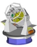
SPeckle Polarimeter: a short description
The stage has three working positions. While it is in position off relay mirrors and linear polarizer are drawn out of the beam and light from the telescope (1) passes to the instrument freely. In position linpol the light from the telescope passes through the linear polarizer (4), which is needed for calibration. In position find one mirror directs light from the telescope to auxiliary camera (4,5), which is used for finding and centering the object. In the meantime second mirror directs light from internal calibration source (7) to the instrument. Rotating half-wave plate (10,11) is used for rotation of polarization plane of incoming radiation, which allows to measure both Stokes parameters describing linear polarization. This is also neeed for realization of spatio-temporal modulation in polarimetry mode. It is possible to change HWP automatically using the special turret (10). In one of positions of this turret the knife diaphragm is installed, it is used for alignment of the axis of rotation stage (11) and center of exit pupil of the instrument. The atmospheric dispersion compensator (ADC) (12, 13; made by RIVoptics ) is also located in parallel beam. The ADC comprise two independently rotatable direct vision prisms (Amici prisms). Each of prisms consists, in turn, of two prisms, one made of F1 glass, another - of K8 glass (Lytkarino). Apex angles of prism components are chosen so that the beam passes through the prism without large deviation, and in the meantime it acquired dispersion. By rotating the prisms one can create the dispersion of any direction and amplitude in some range. This values are set so that the atmospheric dispersion is compensated for current altitude, position angle and in observation wavelength. The standard Bessel filters (Asahi spectra) and middle-band filters centered on 550 (Edmund Optics), 625 (Edmund Optics), and 880 (Thorlabs) nm are installed in filter wheel (14), which is also located in parallel beam. We use Electron Multiplying CCD as a main detector. Detectors of this type are almost free of readout noise (at the price of two-fold increase in photon noise) and allow to obtain series of images with relatively high frame rate (35 frames per second). The detector has quite small amount of cosmetic defects and high quantum efficiency. The instrument has 6 motorized degrees of freedom: 4 rotation stages and 2 actuators (Standa). These drives and main detectorare controlled by software Sparkle2, which runs as daemon in background. Auxiliary camera control software bullseye2 runs in background either. Observer can interact with Sparkle2 and bullseye2 through GUI called specktate or directly, sending text commands over TCP/IP protocol. The first is conventional mode of operation during observations, the second is engineering mode. The series are being saved in FITS datacubes on the control computer. Database is employed for accounting the data. Processing pipeline is written in Matlab. All software (controlling and processing) is stored in git repositories and can be provided on request. The instrument can be mounted both in Cassegrain focus and Nasmyth focus (station 2). The process of mounting takes 2 hours. In both foci the focal ratio of the telescope is the same: F/8. Cassegrain focus is prefferable for precise polarimetry and polaroastrometry. The measurements in other modes can be conducted in Nasmyth focus. Correction of instrumental polarization in Nasmyth is possible down to absolute accuracy of 0.15 percents. Correction for differential polarimetric aberrations (which are important for differential speckle polarimetry) arising at Nasmyth focus is described here. MethodsThe following method can realized with SPeckle Polarimeter:
| ||||
